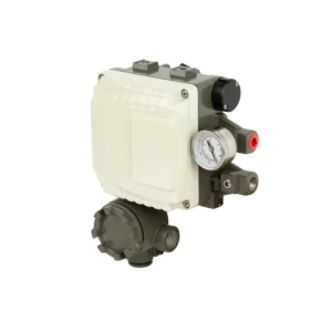
Electro-pneumatic Positioner
A valve positioner is a critical accessory used with control valves to ensure accurate valve operation. It helps precisely position the valve stem or actuator to match the desired control signal, significantly improving process accuracy, response time, and system reliability in automated systems.
Valve positioners are widely used in industries such as oil & gas, chemical, power generation, food & beverage, and pharmaceuticals where precision in flow, pressure, temperature, or level control is essential.
Valve positioners are an indispensable component of any high-performance valve automation system. By precisely controlling valve position in response to control signals, they offer accuracy, repeatability, and system reliability in demanding industrial environments. Whether you’re controlling steam, water, chemicals, or gas, a positioner enhances your system’s responsiveness and safety.
________________________________________
🎯 Function of a Valve Positioner
A valve positioner receives a control signal—typically from a PLC, DCS, or controller—and adjusts the actuator accordingly to position the valve accurately. It compares the input signal (4-20 mA, pneumatic, or digital) to the actual valve position, and compensates for friction, system changes, or actuator backlash.
Without a positioner, the valve may not reach or maintain its intended position—leading to process errors, energy waste, or safety risks.
________________________________________
🧩 Types of Valve Positioners
1. Pneumatic Positioners
• Input: Pneumatic signal (3-15 psi)
• Output: Pneumatic pressure to actuator
• Used in older or air-only systems
• Reliable and simple design
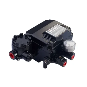
2. Electro-Pneumatic Positioners (E/P)
• Input: Electrical signal (4-20 mA)
• Converts signal into pneumatic output
• Common in modern industrial automation
• Enables precise modulating control
3. Digital/Smart Positioners
• Input: Digital (HART, Foundation Fieldbus, Profibus)
• Integrated with microprocessors
• Allow diagnostics, auto-calibration, remote configuration
• Suitable for complex or safety-critical processes
________________________________________
🔁 Operating Principle
1. The control system sends a setpoint signal.
2. The positioner compares this signal with the actual valve position.
3. If there’s a deviation, the positioner adjusts air pressure to the actuator.
4. This causes the actuator to move until the desired valve position is achieved.
5. Feedback mechanisms ensure closed-loop control.
________________________________________
🔩 Key Components of a Valve Positioner
• Input signal port
• Feedback mechanism (cam or position sensor)
• Pneumatic relay
• Air supply and output ports
• Display (in smart models)
• Manual controls or buttons
• Mounting hardware (to actuator or valve body)
________________________________________
🛠️ Advantages of Using Positioners
• ✅ Improved control accuracy
• ✅ Faster response to signal changes
• ✅ Compensation for friction and valve wear
• ✅ Reduced deadband and hysteresis
• ✅ Enable tight shutoff and modulating service
• ✅ Extend actuator and valve life
• ✅ Diagnostic data for predictive maintenance (smart models)
________________________________________
🧰 Selection Criteria for Valve Positioners
Feature Consideration
Signal Type 3-15 psi, 4-20 mA, digital protocols
Actuator Type Linear or rotary
Mounting Standard NAMUR, IEC 534, or manufacturer-specific
Feedback Type Mechanical cam, potentiometer, or sensor
Explosion Proof? Required in ATEX, IECEx, or SIL zones
Built-in Diagnostics Needed for smart monitoring
Control Mode On/off, modulating, or split-range
________________________________________
🔍 Common Problems Solved by Positioners
Issue Solved With Positioner
Valve does not fully open/close ✔️ Yes
Signal lag or overshoot ✔️ Yes
Unstable valve control ✔️ Yes
Process setpoint not achieved ✔️ Yes
Difficult manual calibration ✔️ Yes (Smart models)
________________________________________
🛠 Installation and Maintenance Tips
• Ensure proper mounting orientation for feedback accuracy.
• Use filtered, dry air for pneumatic models.
• Calibrate during installation or valve changeover.
• Smart models offer auto-calibration and diagnostics.
• Periodically inspect feedback mechanisms and air lines.